


1. Introduction: When Fibre Connectivity Becomes a Bottleneck to AIDC Expansion
As artificial intelligence (AI), high-performance computing (HPC) and large-scale distributed computing advance, data centre networks are evolving towards higher bandwidth, greater port density and larger-scale cluster interconnections. 800G optical transceivers are becoming increasingly common, while 1.6T optical interconnects are beginning to feature in next-generation network designs. In this environment, fibre cabling is more than a means of connecting equipment: it is critical infrastructure that affects network topology, link reliability, deployment efficiency and future scalability.
Traditional data centres typically use fixed port mappings and point-to-point fibre connections. As networks grow, switch port counts increase, or multiple optical channels from high-speed transceivers need to be distributed across different switches or network planes, conventional fibre patching can result in extensive cross-connections, complex cable management and a greater risk of human error.
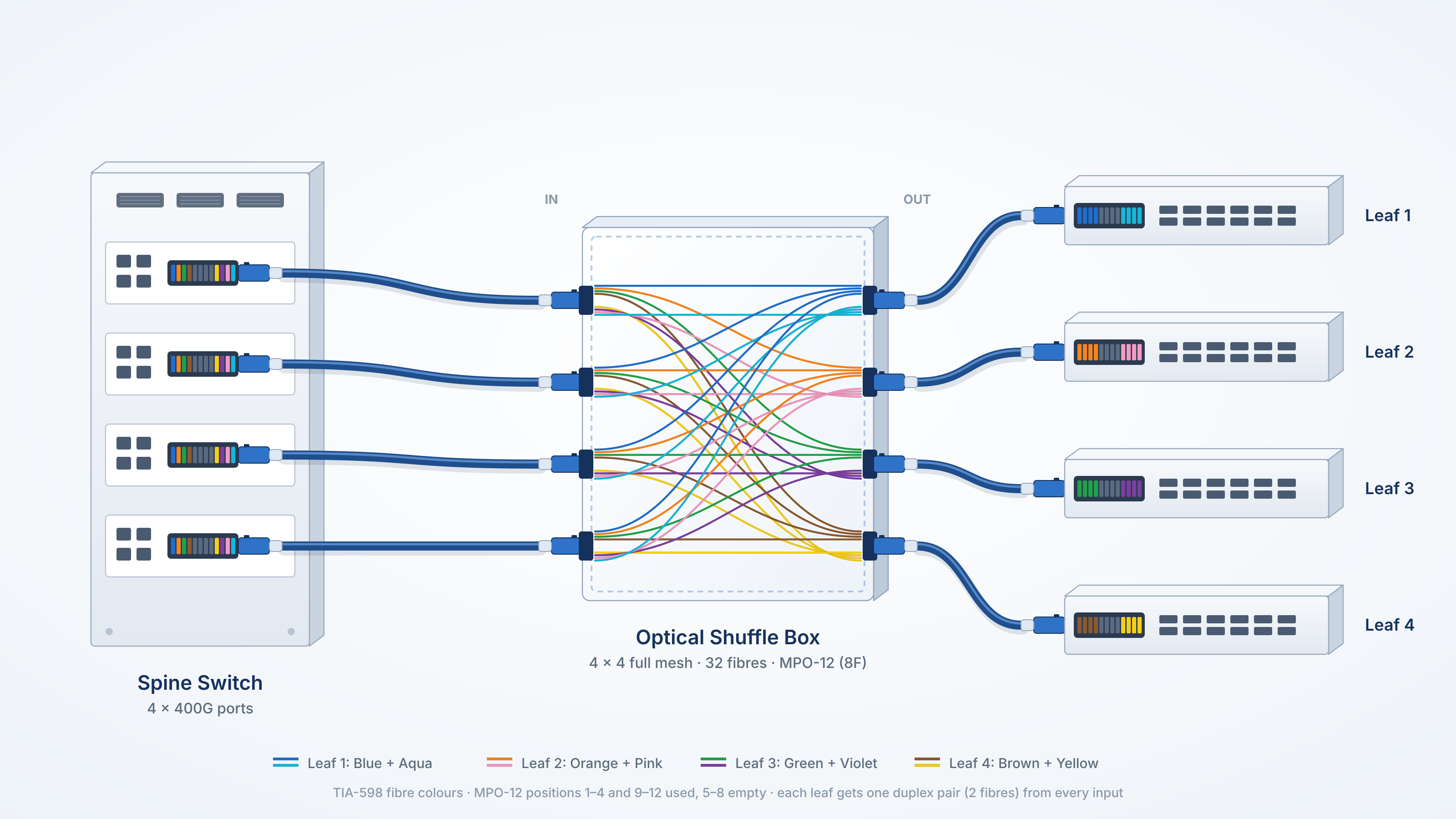
A shuffle solution is a structured cabling approach to rearranging high-density fibre connections. Using a predesigned internal fibre map, it redistributes multiple input optical channels to the appropriate output ports according to predefined rules. This turns complex on-site cross-patching into a fibre connectivity system that can be standardised, factory assembled and deployed repeatedly.
In AI data centres, the value of a shuffle solution extends beyond fibre management. It also provides a clearer, more scalable physical connectivity foundation for leaf-spine networks, multi-plane networks and large-scale AI clusters.
2. The Core Architecture of a Shuffle Solution
2.1 Leaf-Spine Networks Place Greater Demands on Fibre Connectivity
Leaf-spine is one of the most widely used network architectures in modern data centres. Leaf switches connect servers, GPU nodes and other computing equipment, while spine switches form the high-speed backbone interconnecting the leaf switches.
In a typical leaf-spine architecture, each leaf switch requires uplinks to the spine switches in the corresponding network. A properly designed fully interconnected topology can provide relatively consistent forwarding paths, with multiple available paths improving network redundancy and scalability.
As the network grows, connection complexity increases:
- More ports: Each switch may need connections to multiple spine ports or network planes.
- Wider adoption of multi-channel transceivers: A single high-speed optical interface may contain several parallel optical channels that need to be broken out and redistributed according to the network design.
- More cross-connections: Specific port mappings and link distribution requirements for multi-fibre connectors (MPO/MMC/SN-MT) require additional cross-connections.
For leaf-spine cabling, conventional LC patch cord cross-connections and solutions using predesigned shuffle modules differ significantly in cabling complexity, rack space requirements and installation labour costs. Integrating fibre channel distribution into the modules in advance can significantly improve the speed and accuracy of on-site connections.
A shuffle solution is therefore worth considering when a network needs not only to connect equipment, but also to redistribute multiple optical channels according to predefined topology rules.
2.2 From Point-to-Point Connections to Predefined Optical Channel Mapping
The basic principle of a conventional point-to-point connection is straightforward: an input port connects to a specified output port through one fibre or a group of fibres. Changing the connection arrangement usually requires unplugging and reconnecting or rerouting patch cords.
A shuffle solution incorporates this mapping into the product design in advance.
For example, a group of high-speed optical interfaces may contain multiple parallel optical channels. Depending on the network design, these channels may need to connect to different spine switches, port groups or network planes. A shuffle solution redistributes the input and output channels through internally pre-terminated fibres arranged in a specific mapping configuration.
Technical note: A shuffle solution does not mean that optical signals can be switched dynamically between arbitrary ports. In a conventional passive shuffle solution, channel mapping is fixed, and the actual connections are predetermined by the internal product design.
3. What Is a Shuffle Solution?
A shuffle solution is a passive fibre optic solution for managing high-density fibre connections and rearranging optical channels. It typically comprises rack-mounted patch panels and modules.
A typical shuffle solution may include the following components:
Shuffle box
- Input-side multi-fibre connectors (such as MPO)
- Internally pre-terminated fibres with a fixed mapping configuration
- Output-side multi-fibre connectors (such as MPO)
Pre-terminated cables connecting to switches, patch panels and backbone fibre cables.
In practice, the inputs and outputs connect to the corresponding equipment ports or patching ports. The internal fibres are rearranged according to a predefined mapping, bringing connections that would otherwise require multiple individual LC fibre patch cords into a single module.
Technical note: A shuffle solution does not perform optical-to-electrical or electrical-to-optical conversion, nor does it make network routing decisions for switches. Its primary role is to implement predefined connection arrangements at the physical fibre layer.
4. Applications of Shuffle Solutions in AIDC Networks
4.1 Leaf-Spine Switch Interconnections
In a leaf-spine network, a shuffle box can be deployed between the switches and the structured cabling system to distribute optical channels according to predefined mapping rules.
For example, where high-speed uplinks from the leaf side need to be distributed across multiple spine port groups, pre-terminated cables from the leaf side can connect to the shuffle box, with pre-terminated cables on the other side connecting to the designated spine ports.
This approach can reduce the complexity of installing large numbers of individual LC fibre patch cords on site, while making connection mappings easier to document and verify.
Technical note: Whether full interconnection, redundant connections or distribution across line cards can be achieved depends on the switch port configuration, internal optical channel mapping, transceiver type and network topology design. A shuffle solution alone does not determine these capabilities.
4.2 Multi-Plane Networks
Large-scale AI clusters may use multi-plane networks, distributing network connections across independent sets of switches or links.
In this architecture, a shuffle solution can distribute multiple optical channels from high-speed interfaces across different network planes according to a preplanned channel map, supporting the network topology at the physical connectivity layer.
This application places greater demands on mapping accuracy. The following must be defined in advance:
- Which output ports correspond to each input port;
- The network plane to which each optical channel belongs;
- The relationship between equipment ports and transceiver channels;
- Link polarity, connector type and fibre count;
- The amount of bandwidth that could be affected by the failure of a single link.
Technical note: A shuffle solution can help standardise physical connections, but load balancing, failover and traffic scheduling across network planes still depend on the relevant network equipment and software systems.
4.3 800G and 1.6T High-Speed Optical Interconnects
As 800G and 1.6T optical interfaces are adopted, the design of physical connections for high-density parallel optical channels becomes increasingly important.
For example, some 1.6T interface designs can use eight 200G channels to provide a total logical connection capacity of 1.6T. In certain optical shuffle architectures, these channels can be distributed across different spine paths to reduce the impact of a single channel or path failure on total bandwidth.
This capability is not inherent in every shuffle solution. The transceivers, fibre assemblies, switch ports and network topology must all support the required channel breakout and mapping arrangements.
Technical note: During solution design, compatibility must be verified against the specific transceiver interface specifications, channel count, connector pin assignments and link budget. It cannot be determined from the transceiver’s nominal data rate alone.
5. Typical Deployment Approaches for Shuffle Solutions
5.1 Centralised Cabling Between Equipment
In this deployment, shuffle patch panels and modules are installed in a rack or central patching area. Pre-terminated cables from the equipment connect to the shuffle module inputs, while the outputs connect to the destination equipment through additional pre-terminated cables.
This approach suits applications that require centralised management of large numbers of fibre cross-connections, with consistent labelling and maintenance practices.
Its main advantage is a clear physical connection structure, with complex channel mappings consolidated within a standardised module.
5.2 Integration with Backbone Fibre and Structured Cabling
In large data centres, shuffle modules can be used alongside backbone fibre cables, patch panels, MPO/MTP pre-terminated cables and equipment-side patch cords.
A typical connection arrangement is:
Compute node or leaf switch → pre-terminated cable → shuffle module → pre-terminated cable → spine switch or destination network port.
In practice, the inputs and outputs can be reversed or adjusted to suit the network topology. Whether additional MPO-to-LC patch panels and modules are needed on the equipment side also depends on the specific design.
5.3 Use with Shuffle Cables
For applications with clearly defined connection arrangements, short distances or no requirement for centralised module management, a shuffle cable can implement the predefined channel mapping directly.
For larger deployments requiring consistent patching and management by zone, shuffle modules can serve as centralised channel rearrangement units, connecting to the relevant equipment through shuffle cables or conventional pre-terminated cables.
6. Shuffle Modules and Shuffle Cables Compared
Both shuffle modules and shuffle cables can rearrange optical channels, but their physical formats and deployment methods differ.
| Comparison | Shuffle Module | Shuffle Cable |
|---|---|---|
| Mapping | Integrated within a box or module | Integrated within a prefabricated cable assembly |
| Key Advantages | Centralised management, modular deployment and easier maintenance by zone | Direct connection paths, flexible deployment and fewer intermediate components |
| Expansion | Add modules or use higher-density products according to port capacity | Add or replace cables according to link requirements |
| Typical Applications | Structured cabling, centralised fibre rearrangement and inter-rack connections | Direct equipment connections, breakout connections and predefined cross-connections |
The two approaches are not mutually exclusive. In large AI data centres, shuffle modules, shuffle cables or a combination of both can be used according to network scale, rack layout, cabling distances and maintenance requirements.
7. Hermesys HydraX HD Shuffle Solution
Designed for high-density fibre connectivity and predefined channel mapping in data centres, the Hermesys HydraX HD Shuffle Solution combines rack-mounted patch panels with shuffle modules.
7.1 Patch Panels and Modular Configurations
| Product Type | Patch Panel Height | Shuffle Module Configuration | Number of Modules |
|---|---|---|---|
| Type A | 1U | 2×2 (4 Ports/Module) |
8 Modules |
| Type A | 4U | 2×2 (4 Ports/Module) |
32 Modules |
| Type B | 1U | 2×2, 4×4, 8×8 (16F) (16 Ports/Module) |
4 Modules |
| Type B | 4U | 2×2, 4×4, 8×8 (16F) (16 Ports/Module) |
16 Modules |
7.2 Fixed Mapping Management
2×2 Mapping
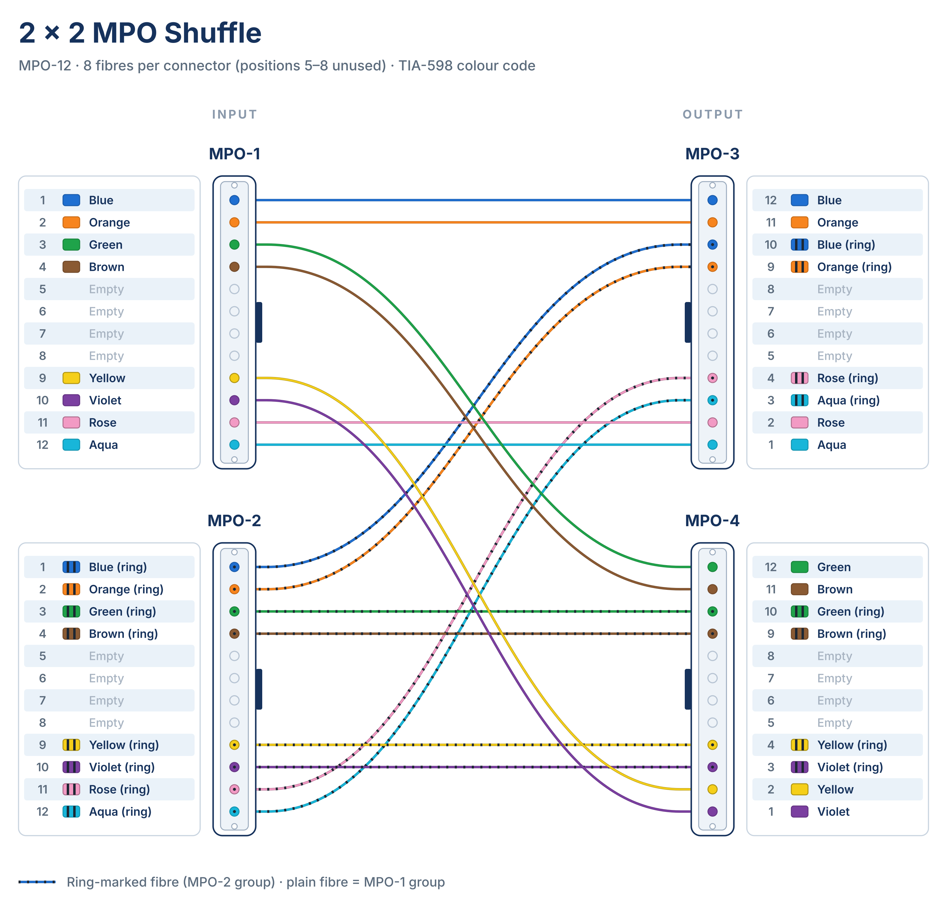
View 2 × 2 fibre mapping table
| Input MPO #1 | Position 1 | Blue #1 | Output MPO #1 | Position 12 | Blue #1 |
| Input MPO #1 | Position 2 | Orange #1 | Output MPO #1 | Position 11 | Orange #1 |
| Input MPO #1 | Position 3 | Green #1 | Output MPO #1 | Position 10 | Blue #2 |
| Input MPO #1 | Position 4 | Brown #1 | Output MPO #1 | Position 9 | Orange #2 |
| Input MPO #1 | Position 5 | - | Output MPO #1 | Position 8 | - |
| Input MPO #1 | Position 6 | - | Output MPO #1 | Position 7 | - |
| Input MPO #1 | Position 7 | - | Output MPO #1 | Position 6 | - |
| Input MPO #1 | Position 8 | - | Output MPO #1 | Position 5 | - |
| Input MPO #1 | Position 9 | Yellow #1 | Output MPO #1 | Position 4 | Pink #2 |
| Input MPO #1 | Position 10 | Violet #1 | Output MPO #1 | Position 3 | Aqua #2 |
| Input MPO #1 | Position 11 | Pink #1 | Output MPO #1 | Position 2 | Pink #1 |
| Input MPO #1 | Position 12 | Aqua #1 | Output MPO #1 | Position 1 | Aqua #1 |
| Input MPO #2 | Position 1 | Blue #2 | Output MPO #2 | Position 12 | Green #1 |
| Input MPO #2 | Position 2 | Orange #2 | Output MPO #2 | Position 11 | Brown #1 |
| Input MPO #2 | Position 3 | Green #2 | Output MPO #2 | Position 10 | Green #2 |
| Input MPO #2 | Position 4 | Brown #2 | Output MPO #2 | Position 9 | Brown #2 |
| Input MPO #2 | Position 5 | - | Output MPO #2 | Position 8 | - |
| Input MPO #2 | Position 6 | - | Output MPO #2 | Position 7 | - |
| Input MPO #2 | Position 7 | - | Output MPO #2 | Position 6 | - |
| Input MPO #2 | Position 8 | - | Output MPO #2 | Position 5 | - |
| Input MPO #2 | Position 9 | Yellow #2 | Output MPO #2 | Position 4 | Yellow #2 |
| Input MPO #2 | Position 10 | Violet #2 | Output MPO #2 | Position 3 | Violet #2 |
| Input MPO #2 | Position 11 | Pink #2 | Output MPO #2 | Position 2 | Yellow #1 |
| Input MPO #2 | Position 12 | Aqua #2 | Output MPO #2 | Position 1 | Violet #1 |
4×4 Mapping
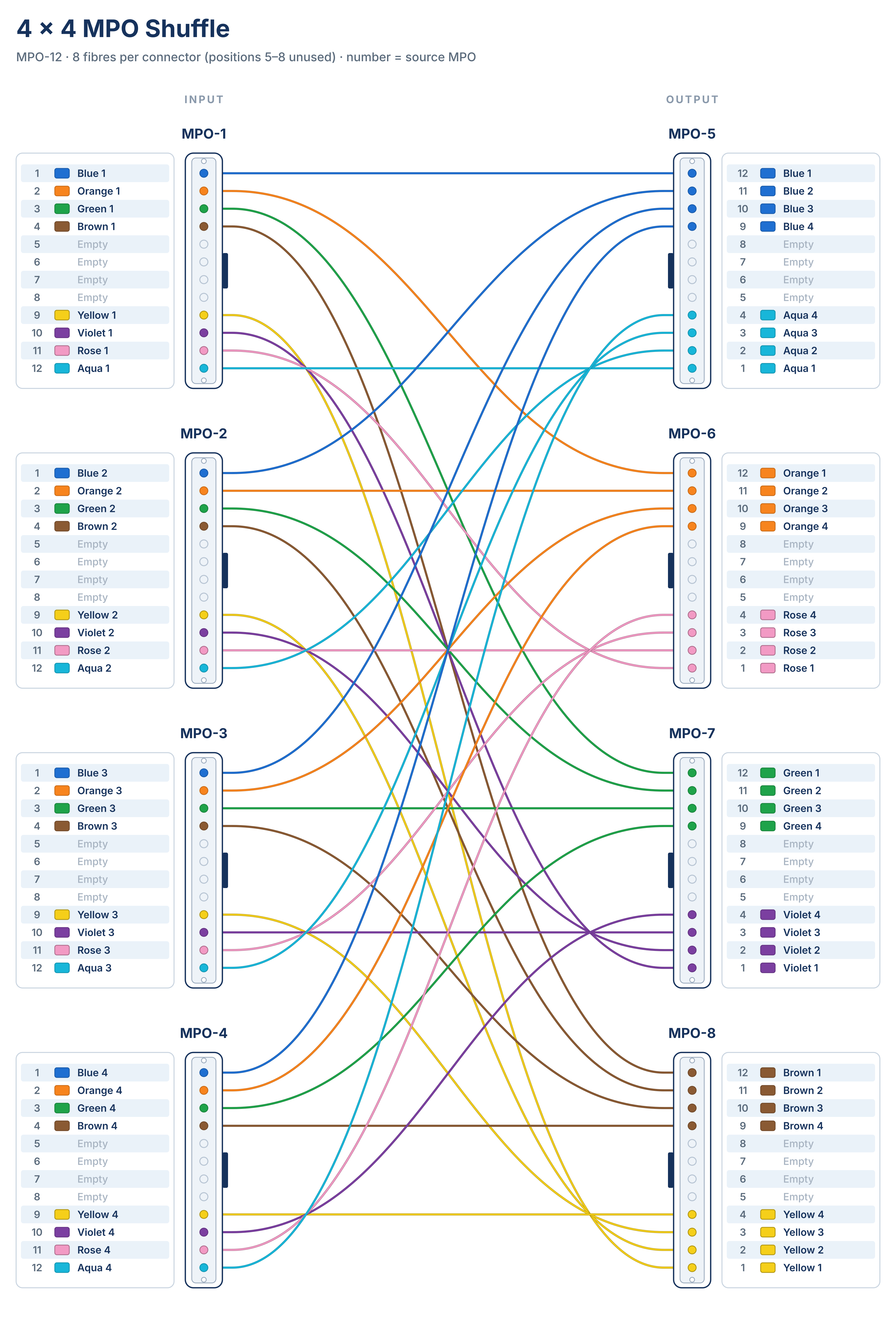
View 4 × 4 fibre mapping table
| Input MPO #1 | Position 1 | Blue #1 | Output MPO #1 | Position 12 | Blue #1 |
| Input MPO #1 | Position 2 | Orange #1 | Output MPO #1 | Position 11 | Blue #2 |
| Input MPO #1 | Position 3 | Green #1 | Output MPO #1 | Position 10 | Blue #3 |
| Input MPO #1 | Position 4 | Brown #1 | Output MPO #1 | Position 9 | Blue #4 |
| Input MPO #1 | Position 5 | - | Output MPO #1 | Position 8 | - |
| Input MPO #1 | Position 6 | - | Output MPO #1 | Position 7 | - |
| Input MPO #1 | Position 7 | - | Output MPO #1 | Position 6 | - |
| Input MPO #1 | Position 8 | - | Output MPO #1 | Position 5 | - |
| Input MPO #1 | Position 9 | Yellow #1 | Output MPO #1 | Position 4 | Aqua #4 |
| Input MPO #1 | Position 10 | Violet #1 | Output MPO #1 | Position 3 | Aqua #3 |
| Input MPO #1 | Position 11 | Pink #1 | Output MPO #1 | Position 2 | Aqua #2 |
| Input MPO #1 | Position 12 | Aqua #1 | Output MPO #1 | Position 1 | Aqua #1 |
| Input MPO #2 | Position 1 | Blue #2 | Output MPO #2 | Position 12 | Orange #1 |
| Input MPO #2 | Position 2 | Orange #2 | Output MPO #2 | Position 11 | Orange #2 |
| Input MPO #2 | Position 3 | Green #2 | Output MPO #2 | Position 10 | Orange #3 |
| Input MPO #2 | Position 4 | Brown #2 | Output MPO #2 | Position 9 | Orange #4 |
| Input MPO #2 | Position 5 | - | Output MPO #2 | Position 8 | - |
| Input MPO #2 | Position 6 | - | Output MPO #2 | Position 7 | - |
| Input MPO #2 | Position 7 | - | Output MPO #2 | Position 6 | - |
| Input MPO #2 | Position 8 | - | Output MPO #2 | Position 5 | - |
| Input MPO #2 | Position 9 | Yellow #2 | Output MPO #2 | Position 4 | Pink #4 |
| Input MPO #2 | Position 10 | Violet #2 | Output MPO #2 | Position 3 | Pink #3 |
| Input MPO #2 | Position 11 | Pink #2 | Output MPO #2 | Position 2 | Pink #2 |
| Input MPO #2 | Position 12 | Aqua #2 | Output MPO #2 | Position 1 | Pink #1 |
| Input MPO #3 | Position 1 | Blue #3 | Output MPO #3 | Position 12 | Green #1 |
| Input MPO #3 | Position 2 | Orange #3 | Output MPO #3 | Position 11 | Green #2 |
| Input MPO #3 | Position 3 | Green #3 | Output MPO #3 | Position 10 | Green #3 |
| Input MPO #3 | Position 4 | Brown #3 | Output MPO #3 | Position 9 | Green #4 |
| Input MPO #3 | Position 5 | - | Output MPO #3 | Position 8 | - |
| Input MPO #3 | Position 6 | - | Output MPO #3 | Position 7 | - |
| Input MPO #3 | Position 7 | - | Output MPO #3 | Position 6 | - |
| Input MPO #3 | Position 8 | - | Output MPO #3 | Position 5 | - |
| Input MPO #3 | Position 9 | Yellow #3 | Output MPO #3 | Position 4 | Violet #4 |
| Input MPO #3 | Position 10 | Violet #3 | Output MPO #3 | Position 3 | Violet #3 |
| Input MPO #3 | Position 11 | Pink #3 | Output MPO #3 | Position 2 | Violet #2 |
| Input MPO #3 | Position 12 | Aqua #3 | Output MPO #3 | Position 1 | Violet #1 |
| Input MPO #4 | Position 1 | Blue #4 | Output MPO #4 | Position 12 | Brown #1 |
| Input MPO #4 | Position 2 | Orange #4 | Output MPO #4 | Position 11 | Brown #2 |
| Input MPO #4 | Position 3 | Green #4 | Output MPO #4 | Position 10 | Brown #3 |
| Input MPO #4 | Position 4 | Brown #4 | Output MPO #4 | Position 9 | Brown #4 |
| Input MPO #4 | Position 5 | - | Output MPO #4 | Position 8 | - |
| Input MPO #4 | Position 6 | - | Output MPO #4 | Position 7 | - |
| Input MPO #4 | Position 7 | - | Output MPO #4 | Position 6 | - |
| Input MPO #4 | Position 8 | - | Output MPO #4 | Position 5 | - |
| Input MPO #4 | Position 9 | Yellow #4 | Output MPO #4 | Position 4 | Yellow #4 |
| Input MPO #4 | Position 10 | Violet #4 | Output MPO #4 | Position 3 | Yellow #3 |
| Input MPO #4 | Position 11 | Pink #4 | Output MPO #4 | Position 2 | Yellow #2 |
| Input MPO #4 | Position 12 | Aqua #4 | Output MPO #4 | Position 1 | Yellow #1 |
8×8 Mapping
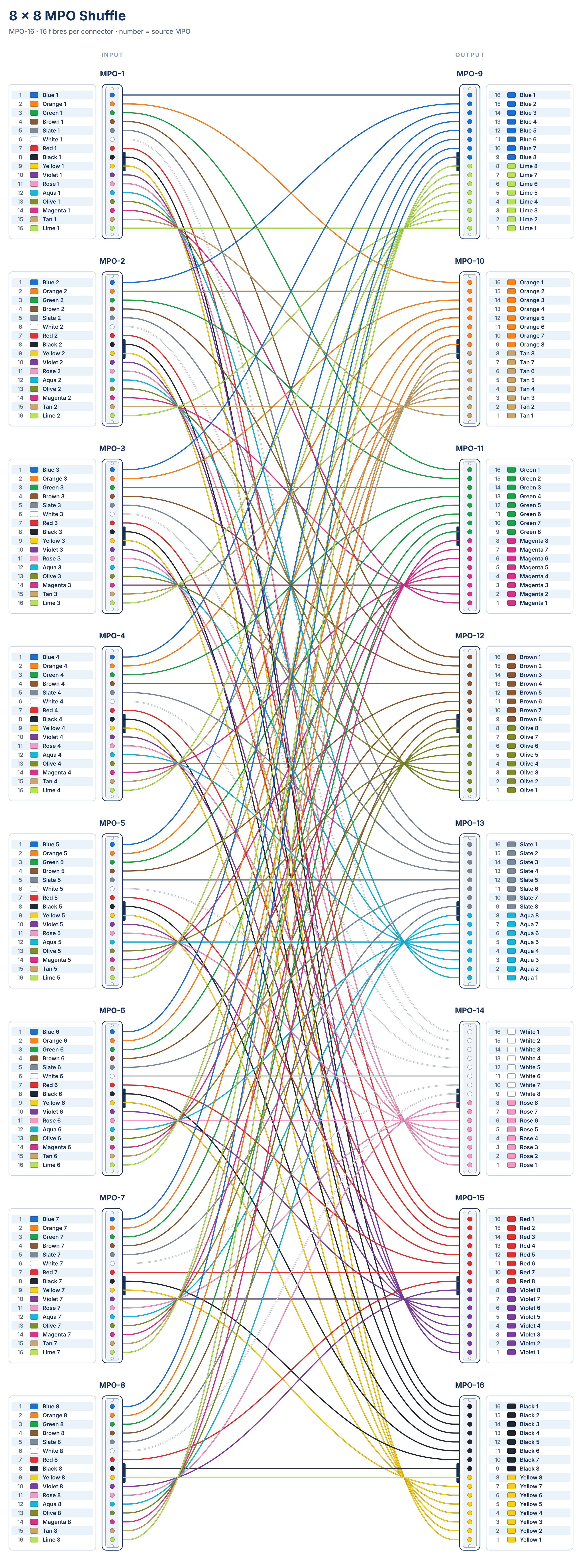
View 8 × 8 fibre mapping table
| Input MPO #1 | Position 1 | Blue #1 | Output MPO #1 | Position 16 | Blue #1 |
| Input MPO #1 | Position 2 | Orange #1 | Output MPO #1 | Position 15 | Blue #2 |
| Input MPO #1 | Position 3 | Green #1 | Output MPO #1 | Position 14 | Blue #3 |
| Input MPO #1 | Position 4 | Brown #1 | Output MPO #1 | Position 13 | Blue #4 |
| Input MPO #1 | Position 5 | Slat #1 | Output MPO #1 | Position 12 | Blue #5 |
| Input MPO #1 | Position 6 | White #1 | Output MPO #1 | Position 11 | Blue #6 |
| Input MPO #1 | Position 7 | Red #1 | Output MPO #1 | Position 10 | Blue #7 |
| Input MPO #1 | Position 8 | Black #1 | Output MPO #1 | Position 9 | Blue #8 |
| Input MPO #1 | Position 9 | Yellow #1 | Output MPO #1 | Position 8 | Lime #8 |
| Input MPO #1 | Position 10 | Violet #1 | Output MPO #1 | Position 7 | Lime #7 |
| Input MPO #1 | Position 11 | Pink #1 | Output MPO #1 | Position 6 | Lime #6 |
| Input MPO #1 | Position 12 | Aqua #1 | Output MPO #1 | Position 5 | Lime #5 |
| Input MPO #1 | Position 13 | Olive #1 | Output MPO #1 | Position 4 | Lime #4 |
| Input MPO #1 | Position 14 | Carmine #1 | Output MPO #1 | Position 3 | Lime #3 |
| Input MPO #1 | Position 15 | Dark Brown #1 | Output MPO #1 | Position 2 | Lime #2 |
| Input MPO #1 | Position 16 | Lime #1 | Output MPO #1 | Position 1 | Lime #1 |
| Input MPO #2 | Position 1 | Blue #2 | Output MPO #2 | Position 16 | Orange #1 |
| Input MPO #2 | Position 2 | Orange #2 | Output MPO #2 | Position 15 | Orange #2 |
| Input MPO #2 | Position 3 | Green #2 | Output MPO #2 | Position 14 | Orange #3 |
| Input MPO #2 | Position 4 | Brown #2 | Output MPO #2 | Position 13 | Orange #4 |
| Input MPO #2 | Position 5 | Slat #2 | Output MPO #2 | Position 12 | Orange #5 |
| Input MPO #2 | Position 6 | White #2 | Output MPO #2 | Position 11 | Orange #6 |
| Input MPO #2 | Position 7 | Red #2 | Output MPO #2 | Position 10 | Orange #7 |
| Input MPO #2 | Position 8 | Black #2 | Output MPO #2 | Position 9 | Orange #8 |
| Input MPO #2 | Position 9 | Yellow #2 | Output MPO #2 | Position 8 | Dark Brown #8 |
| Input MPO #2 | Position 10 | Violet #2 | Output MPO #2 | Position 7 | Dark Brown #7 |
| Input MPO #2 | Position 11 | Pink #2 | Output MPO #2 | Position 6 | Dark Brown #6 |
| Input MPO #2 | Position 12 | Aqua #2 | Output MPO #2 | Position 5 | Dark Brown #5 |
| Input MPO #2 | Position 13 | Olive #2 | Output MPO #2 | Position 4 | Dark Brown #4 |
| Input MPO #2 | Position 14 | Carmine #2 | Output MPO #2 | Position 3 | Dark Brown #3 |
| Input MPO #2 | Position 15 | Dark Brown #2 | Output MPO #2 | Position 2 | Dark Brown #2 |
| Input MPO #2 | Position 16 | Lime #2 | Output MPO #2 | Position 1 | Dark Brown #1 |
| Input MPO #3 | Position 1 | Blue #3 | Output MPO #3 | Position 16 | Green #1 |
| Input MPO #3 | Position 2 | Orange #3 | Output MPO #3 | Position 15 | Green #2 |
| Input MPO #3 | Position 3 | Green #3 | Output MPO #3 | Position 14 | Green #3 |
| Input MPO #3 | Position 4 | Brown #3 | Output MPO #3 | Position 13 | Green #4 |
| Input MPO #3 | Position 5 | Slat #3 | Output MPO #3 | Position 12 | Green #5 |
| Input MPO #3 | Position 6 | White #3 | Output MPO #3 | Position 11 | Green #6 |
| Input MPO #3 | Position 7 | Red #3 | Output MPO #3 | Position 10 | Green #7 |
| Input MPO #3 | Position 8 | Black #3 | Output MPO #3 | Position 9 | Green #8 |
| Input MPO #3 | Position 9 | Yellow #3 | Output MPO #3 | Position 8 | Carmine #8 |
| Input MPO #3 | Position 10 | Violet #3 | Output MPO #3 | Position 7 | Carmine #7 |
| Input MPO #3 | Position 11 | Pink #3 | Output MPO #3 | Position 6 | Carmine #6 |
| Input MPO #3 | Position 12 | Aqua #3 | Output MPO #3 | Position 5 | Carmine #5 |
| Input MPO #3 | Position 13 | Olive #3 | Output MPO #3 | Position 4 | Carmine #4 |
| Input MPO #3 | Position 14 | Carmine #3 | Output MPO #3 | Position 3 | Carmine #3 |
| Input MPO #3 | Position 15 | Dark Brown #3 | Output MPO #3 | Position 2 | Carmine #2 |
| Input MPO #3 | Position 16 | Lime #3 | Output MPO #3 | Position 1 | Carmine #1 |
| Input MPO #4 | Position 1 | Blue #4 | Output MPO #4 | Position 16 | Brown #1 |
| Input MPO #4 | Position 2 | Orange #4 | Output MPO #4 | Position 15 | Brown #2 |
| Input MPO #4 | Position 3 | Green #4 | Output MPO #4 | Position 14 | Brown #3 |
| Input MPO #4 | Position 4 | Brown #4 | Output MPO #4 | Position 13 | Brown #4 |
| Input MPO #4 | Position 5 | Slat #4 | Output MPO #4 | Position 12 | Brown #5 |
| Input MPO #4 | Position 6 | White #4 | Output MPO #4 | Position 11 | Brown #6 |
| Input MPO #4 | Position 7 | Red #4 | Output MPO #4 | Position 10 | Brown #7 |
| Input MPO #4 | Position 8 | Black #4 | Output MPO #4 | Position 9 | Brown #8 |
| Input MPO #4 | Position 9 | Yellow #4 | Output MPO #4 | Position 8 | Olive #8 |
| Input MPO #4 | Position 10 | Violet #4 | Output MPO #4 | Position 7 | Olive #7 |
| Input MPO #4 | Position 11 | Pink #4 | Output MPO #4 | Position 6 | Olive #6 |
| Input MPO #4 | Position 12 | Aqua #4 | Output MPO #4 | Position 5 | Olive #5 |
| Input MPO #4 | Position 13 | Olive #4 | Output MPO #4 | Position 4 | Olive #4 |
| Input MPO #4 | Position 14 | Carmine #4 | Output MPO #4 | Position 3 | Olive #3 |
| Input MPO #4 | Position 15 | Dark Brown #4 | Output MPO #4 | Position 2 | Olive #2 |
| Input MPO #4 | Position 16 | Lime #4 | Output MPO #4 | Position 1 | Olive #1 |
| Input MPO #5 | Position 1 | Blue #5 | Output MPO #5 | Position 16 | Slat #1 |
| Input MPO #5 | Position 2 | Orange #5 | Output MPO #5 | Position 15 | Slat #2 |
| Input MPO #5 | Position 3 | Green #5 | Output MPO #5 | Position 14 | Slat #3 |
| Input MPO #5 | Position 4 | Brown #5 | Output MPO #5 | Position 13 | Slat #4 |
| Input MPO #5 | Position 5 | Slat #5 | Output MPO #5 | Position 12 | Slat #5 |
| Input MPO #5 | Position 6 | White #5 | Output MPO #5 | Position 11 | Slat #6 |
| Input MPO #5 | Position 7 | Red #5 | Output MPO #5 | Position 10 | Slat #7 |
| Input MPO #5 | Position 8 | Black #5 | Output MPO #5 | Position 9 | Slat #8 |
| Input MPO #5 | Position 9 | Yellow #5 | Output MPO #5 | Position 8 | Aqua #8 |
| Input MPO #5 | Position 10 | Violet #5 | Output MPO #5 | Position 7 | Aqua #7 |
| Input MPO #5 | Position 11 | Pink #5 | Output MPO #5 | Position 6 | Aqua #6 |
| Input MPO #5 | Position 12 | Aqua #5 | Output MPO #5 | Position 5 | Aqua #5 |
| Input MPO #5 | Position 13 | Olive #5 | Output MPO #5 | Position 4 | Aqua #4 |
| Input MPO #5 | Position 14 | Carmine #5 | Output MPO #5 | Position 3 | Aqua #3 |
| Input MPO #5 | Position 15 | Dark Brown #5 | Output MPO #5 | Position 2 | Aqua #2 |
| Input MPO #5 | Position 16 | Lime #5 | Output MPO #5 | Position 1 | Aqua #1 |
| Input MPO #6 | Position 1 | Blue #6 | Output MPO #6 | Position 16 | White #1 |
| Input MPO #6 | Position 2 | Orange #6 | Output MPO #6 | Position 15 | White #2 |
| Input MPO #6 | Position 3 | Green #6 | Output MPO #6 | Position 14 | White #3 |
| Input MPO #6 | Position 4 | Brown #6 | Output MPO #6 | Position 13 | White #4 |
| Input MPO #6 | Position 5 | Slat #6 | Output MPO #6 | Position 12 | White #5 |
| Input MPO #6 | Position 6 | White #6 | Output MPO #6 | Position 11 | White #6 |
| Input MPO #6 | Position 7 | Red #6 | Output MPO #6 | Position 10 | White #7 |
| Input MPO #6 | Position 8 | Black #6 | Output MPO #6 | Position 9 | White #8 |
| Input MPO #6 | Position 9 | Yellow #6 | Output MPO #6 | Position 8 | Pink #8 |
| Input MPO #6 | Position 10 | Violet #6 | Output MPO #6 | Position 7 | Pink #7 |
| Input MPO #6 | Position 11 | Pink #6 | Output MPO #6 | Position 6 | Pink #6 |
| Input MPO #6 | Position 12 | Aqua #6 | Output MPO #6 | Position 5 | Pink #5 |
| Input MPO #6 | Position 13 | Olive #6 | Output MPO #6 | Position 4 | Pink #4 |
| Input MPO #6 | Position 14 | Carmine #6 | Output MPO #6 | Position 3 | Pink #3 |
| Input MPO #6 | Position 15 | Dark Brown #6 | Output MPO #6 | Position 2 | Pink #2 |
| Input MPO #6 | Position 16 | Lime #6 | Output MPO #6 | Position 1 | Pink #1 |
| Input MPO #7 | Position 1 | Blue #7 | Output MPO #7 | Position 16 | Red #1 |
| Input MPO #7 | Position 2 | Orange #7 | Output MPO #7 | Position 15 | Red #2 |
| Input MPO #7 | Position 3 | Green #7 | Output MPO #7 | Position 14 | Red #3 |
| Input MPO #7 | Position 4 | Brown #7 | Output MPO #7 | Position 13 | Red #4 |
| Input MPO #7 | Position 5 | Slat #7 | Output MPO #7 | Position 12 | Red #5 |
| Input MPO #7 | Position 6 | White #7 | Output MPO #7 | Position 11 | Red #6 |
| Input MPO #7 | Position 7 | Red #7 | Output MPO #7 | Position 10 | Red #7 |
| Input MPO #7 | Position 8 | Black #7 | Output MPO #7 | Position 9 | Red #8 |
| Input MPO #7 | Position 9 | Yellow #7 | Output MPO #7 | Position 8 | Violet #8 |
| Input MPO #7 | Position 10 | Violet #7 | Output MPO #7 | Position 7 | Violet #7 |
| Input MPO #7 | Position 11 | Pink #7 | Output MPO #7 | Position 6 | Violet #6 |
| Input MPO #7 | Position 12 | Aqua #7 | Output MPO #7 | Position 5 | Violet #5 |
| Input MPO #7 | Position 13 | Olive #7 | Output MPO #7 | Position 4 | Violet #4 |
| Input MPO #7 | Position 14 | Carmine #7 | Output MPO #7 | Position 3 | Violet #3 |
| Input MPO #7 | Position 15 | Dark Brown #7 | Output MPO #7 | Position 2 | Violet #2 |
| Input MPO #7 | Position 16 | Lime #7 | Output MPO #7 | Position 1 | Violet #1 |
| Input MPO #8 | Position 1 | Blue #8 | Output MPO #8 | Position 16 | Black #1 |
| Input MPO #8 | Position 2 | Orange #8 | Output MPO #8 | Position 15 | Black #2 |
| Input MPO #8 | Position 3 | Green #8 | Output MPO #8 | Position 14 | Black #3 |
| Input MPO #8 | Position 4 | Brown #8 | Output MPO #8 | Position 13 | Black #4 |
| Input MPO #8 | Position 5 | Slat #8 | Output MPO #8 | Position 12 | Black #5 |
| Input MPO #8 | Position 6 | White #8 | Output MPO #8 | Position 11 | Black #6 |
| Input MPO #8 | Position 7 | Red #8 | Output MPO #8 | Position 10 | Black #7 |
| Input MPO #8 | Position 8 | Black #8 | Output MPO #8 | Position 9 | Black #8 |
| Input MPO #8 | Position 9 | Yellow #8 | Output MPO #8 | Position 8 | Yellow #8 |
| Input MPO #8 | Position 10 | Violet #8 | Output MPO #8 | Position 7 | Yellow #7 |
| Input MPO #8 | Position 11 | Pink #8 | Output MPO #8 | Position 6 | Yellow #6 |
| Input MPO #8 | Position 12 | Aqua #8 | Output MPO #8 | Position 5 | Yellow #5 |
| Input MPO #8 | Position 13 | Olive #8 | Output MPO #8 | Position 4 | Yellow #4 |
| Input MPO #8 | Position 14 | Carmine #8 | Output MPO #8 | Position 3 | Yellow #3 |
| Input MPO #8 | Position 15 | Dark Brown #8 | Output MPO #8 | Position 2 | Yellow #2 |
| Input MPO #8 | Position 16 | Lime #8 | Output MPO #8 | Position 1 | Yellow #1 |
8. Conclusion: Making High-Density Fibre Connectivity a System That Can Be Designed and Managed
As AI data centres evolve towards higher bandwidth, larger scale and more complex multi-plane networks, the design and management of fibre connectivity are becoming an increasingly important part of data centre infrastructure.
Through predefined optical channel mapping, centralised connection management and pre-terminated assemblies, a shuffle solution turns complex fibre cross-connections into a more standardised cabling system. For leaf-spine networks and AI clusters that require extensive rearrangement of high-speed optical channels, it can help reduce on-site cabling complexity, improve connection management and provide a clearer physical connectivity foundation for future expansion.
To plan a shuffle layout for your AI cluster, talk to our fibre optic technical support team.