


Pre-terminated fiber in LC and MPO/MTP® for high-fiber-count data centre links. Choose the interface that matches your optics, then the deployment method that matches your ducts, from factory-terminated trunks to air-blown micro cable terminated on site.
Two interfaces, one backbone strategy
At hyperscale fibre counts, how the cable gets into the duct matters as much as the cable itself, and the connector at the end has to match the optics. Duplex optics land on LC. Parallel optics at 400G, 800G and 1.6T land on MPO.
| Criteria | LC solution | MPO/MTP® solution |
|---|---|---|
| Connectors per 576 fibres | 576 LC simplex | 48 MPO-12 or 24 MPO-24 |
| Native transceiver interface | Duplex LC optics (SR, LR, FR4) | Parallel optics (DR4, SR8, 2×DR4), plus LC via cassettes |
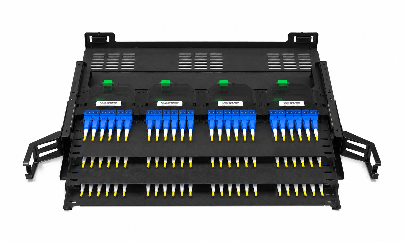
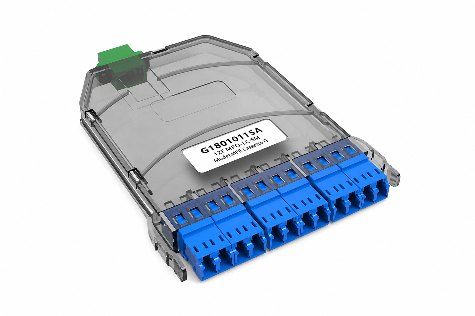
| Patch panel | 576F 4U pull-through LC panel | MPO cassette panels, 144F to 864F per 1U |
| Connector bundle in the duct | ≥ 60 mm for 576 LC fanouts | Far smaller: 48 or 24 compact MPO legs |
| Polarity planning | Simple (A-B per duplex) | Required (Method A, B or C, kept consistent end to end) |
| Upgrade path | Re-patch per fibre pair | Swap cassettes or jumpers, keep the trunk |
| Best fit | Duplex-optic networks, maximum per-port flexibility | 400G–1.6T spine-leaf, AI and GPU clusters |
MPO loss per mated pair from HydraX™ trunk specifications: low-loss SM ≤ 0.35 dB, low-loss MM ≤ 0.25 dB.
LC Solution
The reference design links a core building to three surrounding buildings over two diverse routes each, at 430 m to 930 m. Each route carries 29,376 to 112,320 fibres as 576-fiber cables, terminated LC-LC on 576F 4U patch panels in 42U racks: 1,344 panels and 152 racks in total.
Three ways to build it
Factory pre-terminated assemblies
576 LC simplex connectors are fitted and tested in the factory on staggered fanouts, then the whole assembly is pulled into the duct.
- Lowest link loss, factory-tested connectors
- No splicing or termination labour on site
- LC bundle needs a pulling head of at least 60 mm, so only about 6 cables fit per 100 mm duct
- High risk of damaging fanouts or connectors on long manual pulls; one broken fibre means replacing or splicing the whole trunk
- Staggered fanouts from 350 to 1,500 mm are hard to manage inside the panel
Air-blown cable + on-site connectors
576F micro cable is blown into 20/16 mm low-friction microducts, then LC connectors are terminated after the cable reaches the building.
- Same low link loss as pre-terminated
- No pulling force on the cable; connectors never travel through the duct
- 15 microducts per 100 mm duct, the highest duct utilisation
- Fanout lengths cut to the real rack and panel positions
- Field termination is slower: about 60 days on site vs 30–40 days in factory at this scale
- Higher cost than factory termination
Air-blown cable + spliced pigtails
The same blown micro cable, fusion spliced to factory-made LC pigtails inside the high-density 576F 4U patch panel.
- Same duct savings and zero pulling risk as option 02
- Pigtail splicing is easier to manage than field connectorisation
- Splicing by the customer's team, or by Hermesys engineers
- About 0.2 dB higher loss per link (two splices)
- Higher on-site labour cost than factory termination
Sixty percent fewer ducts
A pre-terminated 576F cable has to drag its connector bundle through the duct. Air-blown micro cable travels bare, so one 100 mm duct can be divided into fifteen 20/16 mm microducts, each carrying a 576F cable.
What 576 connectors look like
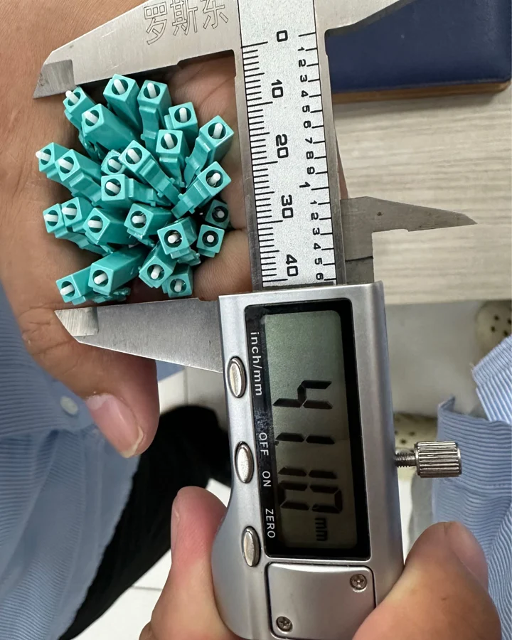
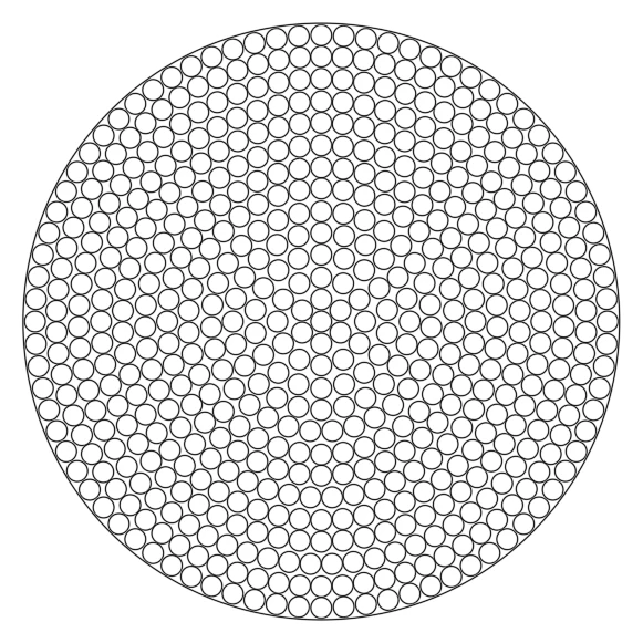
Just 24 LC simplex connectors measure about 41 mm across. Scale that to 576 connectors on staggered fanouts and the protected bundle reaches at least 60 mm before any pulling grip is added. The 576 × 900 µm fanout tubes alone form a bundle of roughly 26 mm.
That is the core trade-off: factory termination gives you tested connectors, but those connectors then have to survive the pull.
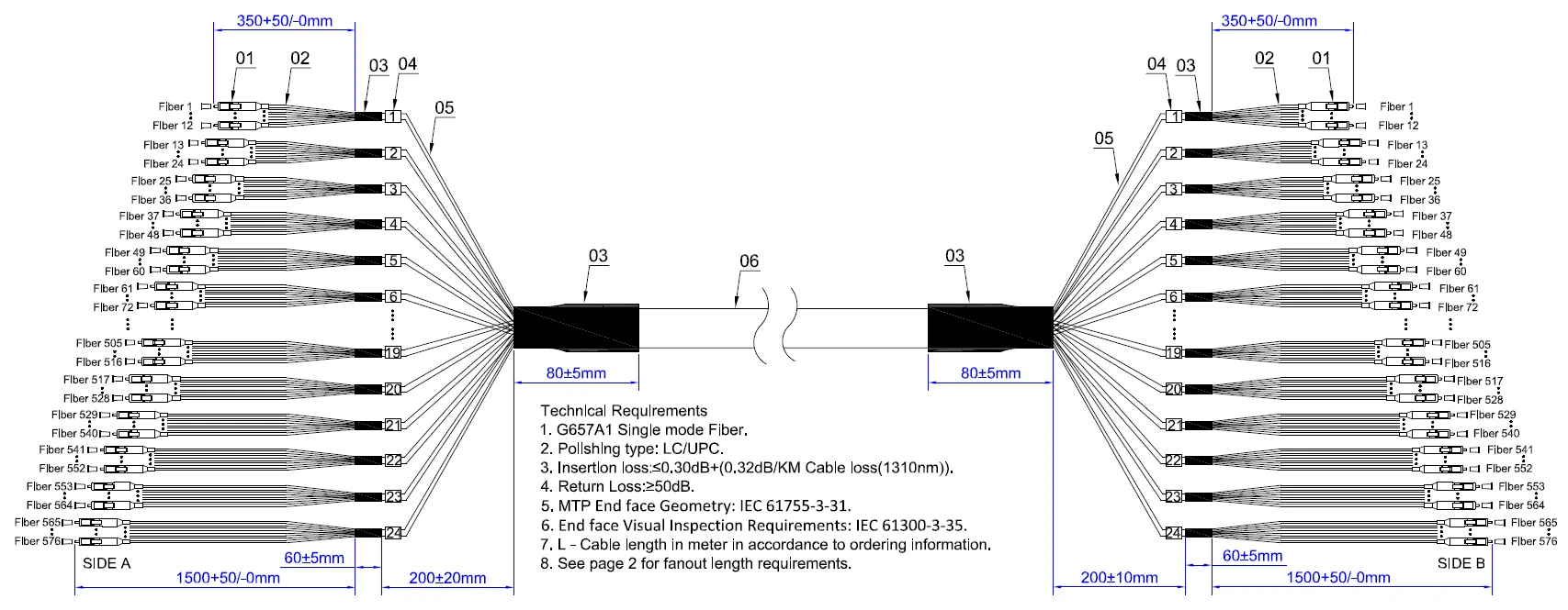
Inside a 576F LC pre-terminated assembly
Hermesys production drawing. Each end breaks out into 24 legs of 24 fibres, with staggered fanout lengths from 350 mm to 1,500 mm so the connectors can be bundled for pulling.
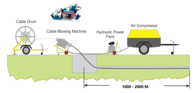
How air-blown installation works
A cable blowing machine pushes the micro cable into the microduct while compressed air floats it along the duct wall, so the cable is carried rather than pulled. Hermesys teams install with our own blowing equipment, at around 60 m/min.
Side by side
| Criteria | 01 · Pre-terminated | 02 · Blown + connectors | 03 · Blown + pigtails |
|---|---|---|---|
| Estimated link loss (LC-LC) | 0.76–0.93 dB | 0.76–0.93 dB | 0.96–1.13 dB |
| Cables per 100 mm duct | ≈ 6 | 15 (in microducts) | 15 (in microducts) |
| 100 mm ducts, all six routes | 114 | 46 | 46 |
| Stress on cable during install | High (manual pull with connectors) | None (air-blown) | None (air-blown) |
| Connector damage risk in duct | High | Không | Không |
| Fanout length fit to rack | Fixed in factory (350–1,500 mm) | Cut to site | Cut to site |
| On-site labour | Lowest | Highest (field connectors) | Medium (fusion splicing) |
| Cost of termination | Lowest | Cao Hơn | Cao Hơn |
Link loss figures are estimates for the reference design. Option 03 includes two fusion splices per link (≈ 0.2 dB).
Route by route
576F cables on 576F 4U patch panels at both ends, LC-LC throughout.
| Link | Route | Fibres | Panels / racks (each end) | Cable length | Ducts: 01 / 02–03 | Loss: 01–02 / 03 |
|---|---|---|---|---|---|---|
| Building B → A | 430 m | 112,320 | 195 / 22 | 83,850 m | 33 / 13 | 0.76 / 0.96 dB |
| Building B → A | 780 m | 112,320 | 195 / 22 | 152,100 m | 33 / 13 | 0.88 / 1.08 dB |
| Building D → A | 830 m | 29,376 | 51 / 6 | 42,330 m | 9 / 4 | 0.90 / 1.10 dB |
| Building D → A | 590 m | 29,376 | 51 / 6 | 30,090 m | 9 / 4 | 0.82 / 1.02 dB |
| Building C → A | 930 m | 51,840 | 90 / 10 | 83,700 m | 15 / 6 | 0.93 / 1.13 dB |
| Building C → A | 730 m | 51,840 | 90 / 10 | 65,700 m | 15 / 6 | 0.86 / 1.06 dB |
Indicative lead times
01 · Pre-terminated
02 · Blown + connectors
03 · Blown + pigtails
Lead times are for the full reference project (1,344 panels, 152 racks) and vary with order size and factory schedule.
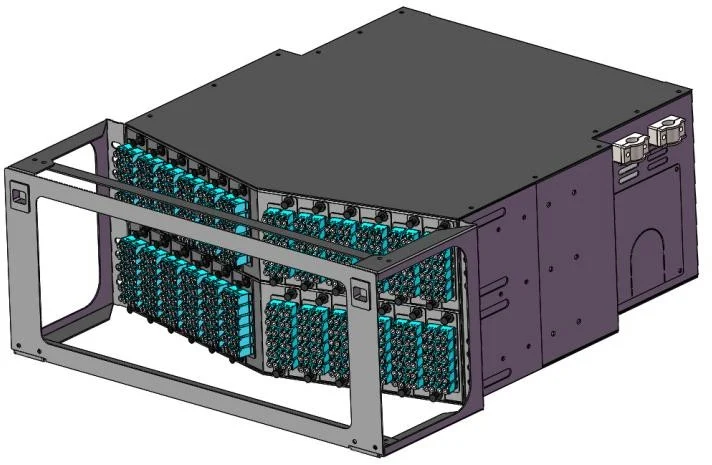
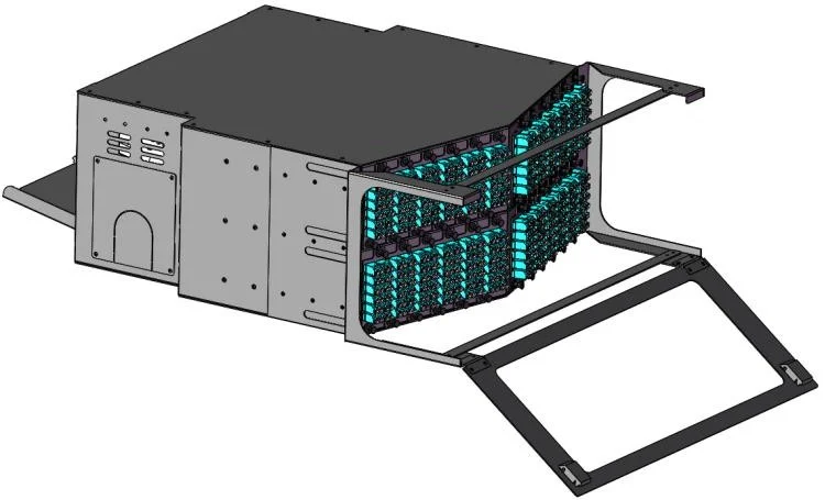
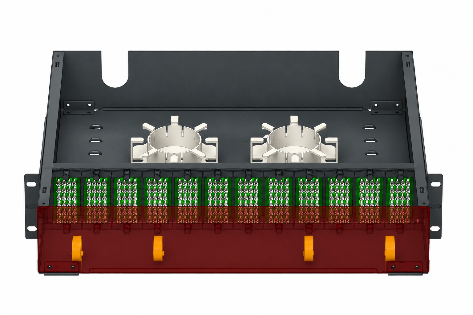
576F 4U high-density patch panel
Pull-through distribution. All three approaches land on the same panel, so the deployment method can change per route without changing the rack design.
- Standard 19" mounting, 4U height
- Up to 576 fibres with LC connectors
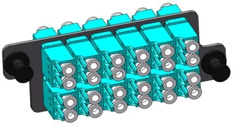
- 24F LC faceplate modules
- Fixed type for easy installation and management
- Precision sheet-metal construction with a durable coated finish
- Integrated fibre management and structural accessories
MPO/MTP® Solution
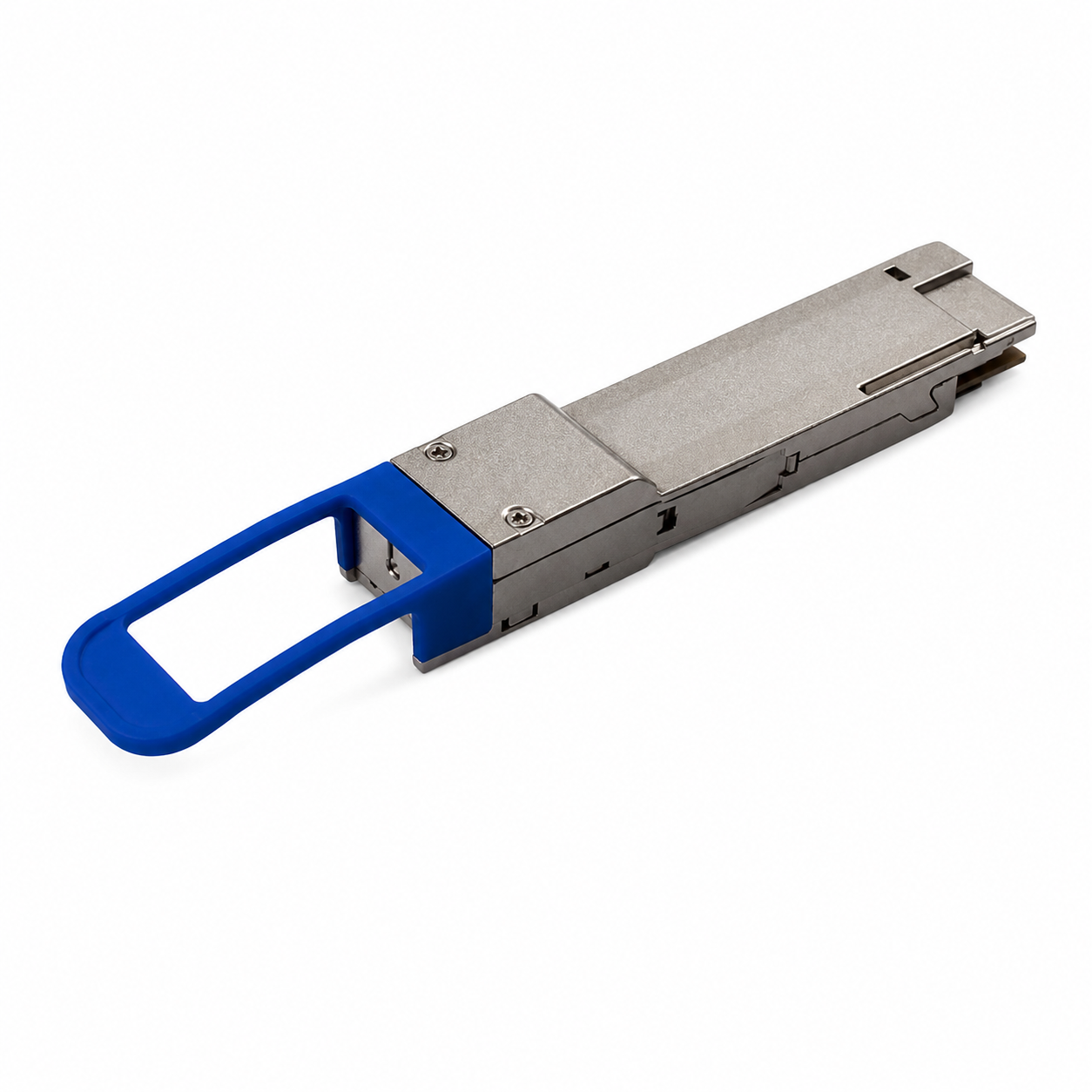
400G DR4, 800G SR8 and 1.6T 2×DR4 transceivers are parallel optics: they transmit over several fibre pairs at once through a single multi-fibre connector. An MPO backbone matches that interface end to end, so there is no fan-out to LC in the middle of the link.
For the same fibre count, an MPO-terminated cable has twelve to twenty-four times fewer connectors to fit, clean, inspect and pull than an LC-terminated one. That is why pre-terminated MPO trunks have become the default for new AI and cloud data halls.
How the MPO link is built
The trunk stays fixed. What changes at each end is only the cassette or jumper, so the same backbone serves today's optics and the next generation.
Two ways to get MPO between buildings
Factory MPO trunk, pulled
MPO-to-MPO trunk cables are terminated and tested in the factory, then pulled into the duct with a protected pulling grip.
- Fastest to commission, no splicing on site
- Every leg factory-tested for insertion and return loss
- A much smaller connector bundle than 576 LC fanouts
- Trunk lengths must be measured accurately before production
- Connectors still travel through the duct during the pull
Air-blown cable + MPO pigtails, spliced
High-fiber-count cable is blown into microducts, then factory-made MPO pigtails are spliced inside the panel at each end.
- Keeps the duct savings of air-blown installation
- No connector can be damaged during installation
- Cable lengths are cut to site, so no length risk
- Adds two splices per link
- Needs on-site splicing, by your team or Hermesys engineers
Plan the optics by route length
Parallel single-mode optics such as 400G DR4 and 1.6T 2×DR4 are specified to 500 m. Campus routes often run longer.
On a typical multi-building campus with routes from 430 m to 930 m, the shorter links can run DR4-class optics directly over an MPO backbone, while the longer ones need 2 km optics, many of which use duplex LC.
An MPO trunk with cassettes covers both: present MPO at the panel for parallel optics, or swap in an MPO-to-LC cassette for duplex optics, without touching the trunk.
- ≤ 500 m · 400G DR4, 1.6T 2×DR4 over MPO-12/APC
- ≤ 100 m · 800G SR8 over multimode MPO
- Lên đến 2 km · 2 km optics such as FR4, via MPO-to-LC cassettes
- Any length · the same MPO trunk and panel
Products in these solutions
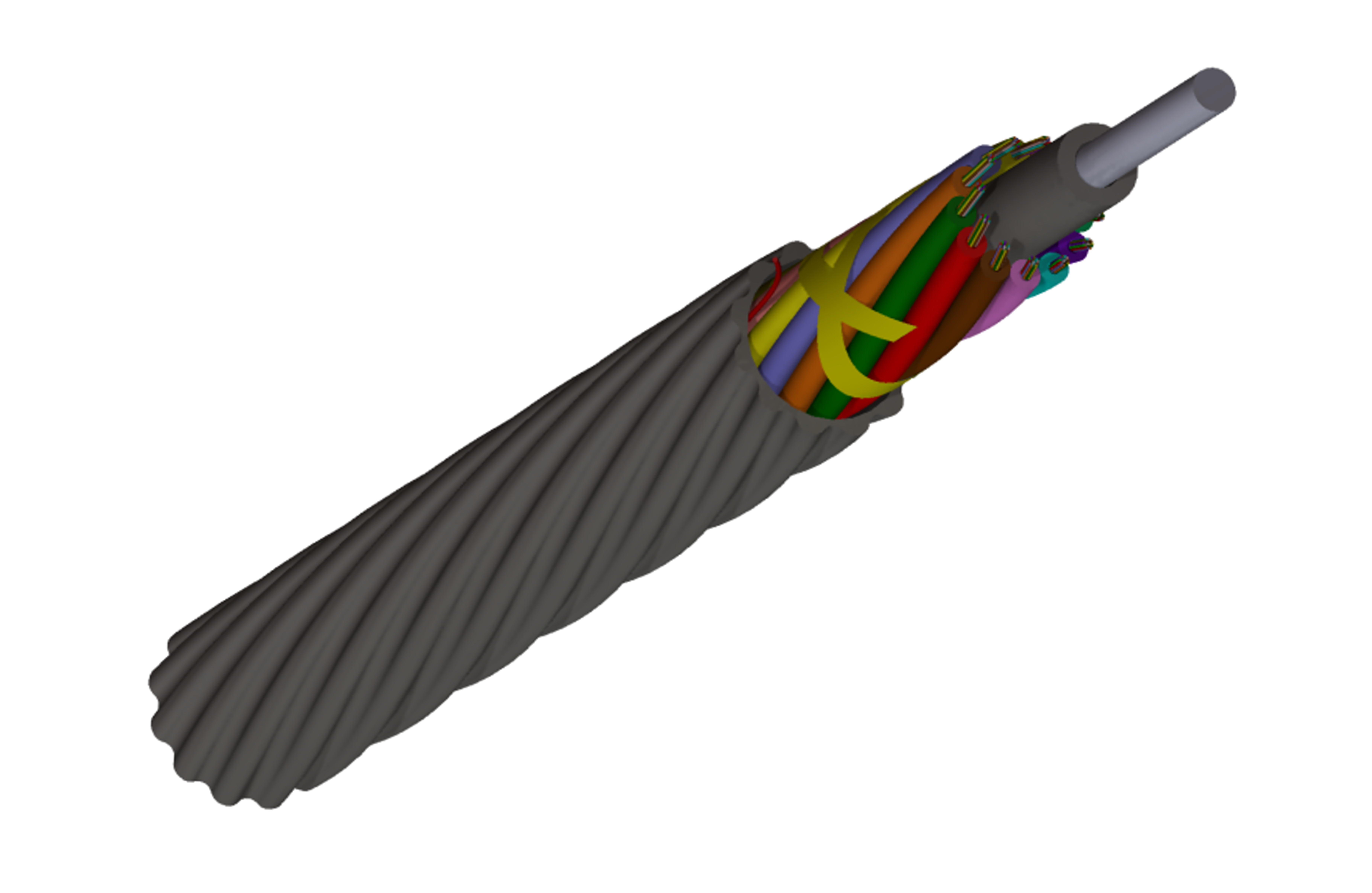
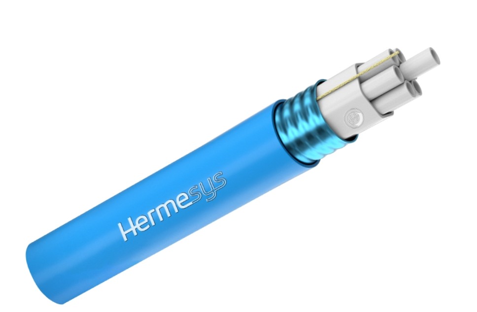
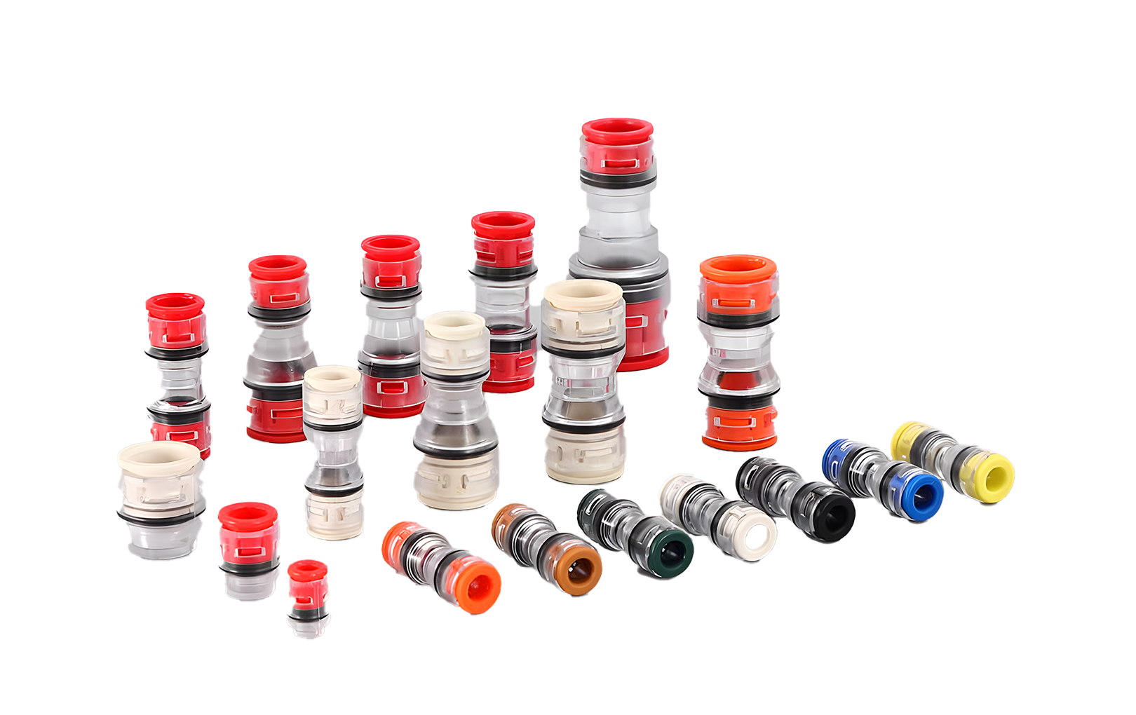
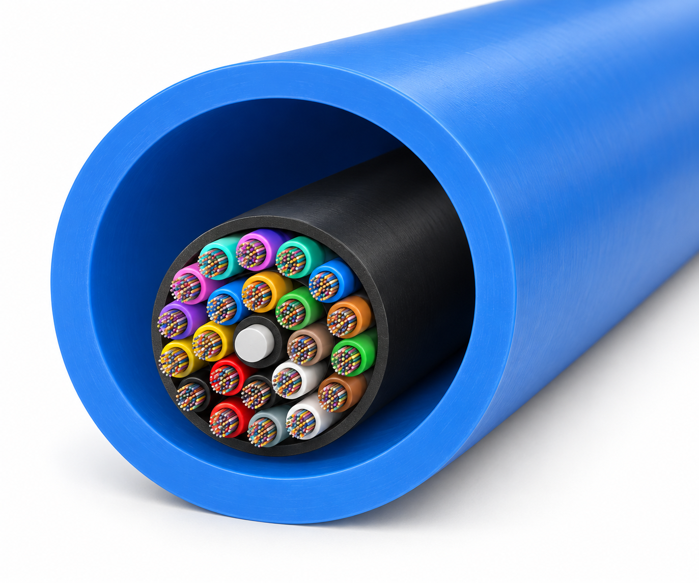
Everything in both solutions is supplied by Hermesys, from the duct to the transceiver.
LC solution



MPO/MTP® solution





Which solution fits your project
LC · Pre-terminated
Routes are short and straight, duct space is plentiful, and you want the fastest commissioning with the least skilled labour on site.
LC · Blown + connectors
Duct space is limited, routes are long or have many bends, and you need the lowest loss with fanouts cut exactly to the rack layout.
LC · Blown + pigtails
You want the duct savings and installation safety of air-blown cable, have splicing capacity, and can accept about 0.2 dB extra per link.
MPO · Trunk, pulled
Parallel optics at 400G and above, accurately surveyed routes and a priority on fast, plug-and-play commissioning.
MPO · Via air-blown cable
Duct space is tight or routes are long and complex, and you want MPO at the panel without pulling connectors through the duct.
Frequently asked questions
What is an MPO/MTP pre-terminated trunk cable?
It is a multi-fibre cable with MPO or MTP® connectors fitted and tested in the factory. Each connector terminates 12, 16 or 24 fibres, so a single trunk can deliver hundreds of fibres that are ready to plug into patch panels and cassettes without splicing on site.
Is pre-terminated fiber better than field-terminated fiber?
Not always. Pre-terminated assemblies give the lowest link loss and least site labour, but large connector bundles take more duct space and are vulnerable during long pulls. For high-fiber-count links between buildings, air-blown micro cable with on-site termination can match the loss while using about 60% fewer ducts.
How many microducts fit in a 100 mm duct?
At least fifteen 20/16 mm low-friction microducts fit in one 100 mm duct, each able to carry a 576-fiber air-blown micro cable. A 100 mm duct takes only about six pre-terminated 576F cables because of the 60 mm connector bundle.
How much loss does splicing pigtails add?
Splicing LC pigtails at both ends adds two fusion splices per link, roughly 0.2 dB in total. In the reference design this raises estimated LC-LC link loss from 0.76–0.93 dB to 0.96–1.13 dB.
How fast can air-blown micro cable be installed?
With a cable blowing machine, 576F micro cable can be installed at around 60 metres per minute, without pulling tension on the cable. Hermesys teams can carry out the blowing with our own equipment.
What is the difference between MPO and MTP?
MPO is the generic multi-fibre push-on connector standard. MTP® is a high-performance version of the MPO connector made by US Conec and is fully compatible with MPO interfaces.
Why do 400G and 800G transceivers use MPO connectors?
Parallel optics such as 400G DR4, 800G SR8 and 1.6T 2×DR4 send data over several fibre lanes at the same time. A single MPO connector carries all of those lanes, which keeps the port compact and the cabling simple.
What is MPO polarity?
Polarity makes sure each transmitter connects to the matching receiver at the far end. MPO systems use Method A, B or C, and the trunks, cassettes and jumpers must follow the same method end to end. HydraX™ trunks are available in polarity A or B.
Should single-mode MPO connectors be APC?
For single-mode parallel optics, angled (APC) MPO connectors are standard because they give high return loss. HydraX™ single-mode APC MPO connectors are rated at 55 dB return loss or better.
Planning a data centre build?
Send us your optics, fibre counts and route lengths. Our engineers will recommend LC or MPO for each link and size the ducts, trunks, cassettes, panels and racks.
Talk to our engineers Explore HydraX™